
Create Animation using Mate Controller
Mate controller allows you to control over the movement of your assembly by adjusting some specific mates position.
Using mate controller, you can specify positions to your assembly components using mate values which use configuration for each position.
We can apply Mate Controller to fully defined assemblies, by changing various mate values but animation can only be used only for under defined assemblies (Mate must be open as per application requirements.)
The SOLIDWORKS mate controller is also integrated with motion studies, so you can create animations based on the positions you have defined with the mate controller, thus making the process of animating movement much easier.
Supported mates for Mate Controller:
- Angle
- Distance
- Limit Angle
- Limit Distance
- Slot (Distance along slot, percent along slot)
- Width (Dimension, Percent)
- Path (Distance along path, percent along path)
How to apply Mate Controller:
We will use the following example of Pick and Place assembly which have the Limit distance mates as shown in Fig. 1.

Use of Mate Controller
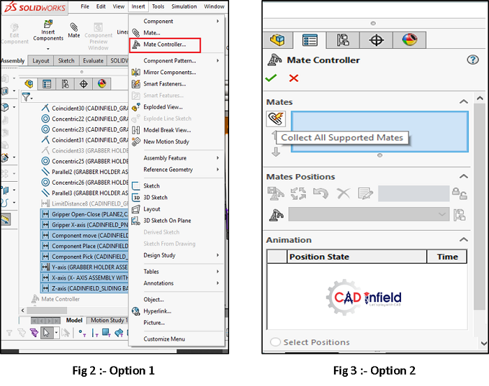
Option 1: –
- Select the all required mates and then go the
- Click “Insert Menu”
- Select “Mate Controller” as shown in Fig.
Option 2: –
- Click “Insert menu”
- Select “Mate Controller” and Mate controller window will pop-up.
- Click “Collect all supported mates” then SolidWorks will automatically collect supported mates (Shown in Fig. 3).
We can keep required mates by deleting unrequited mates.
Tip: Assign meaningful names to the specific mates which we want to apply mate controller. So, you won’t end up with menu filled with limit angle 1, limit angle 2 etc.
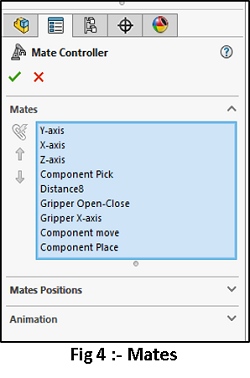
Mate Controller window:
The menu has three sections viz; Mates, Mates position and Animation as shown in Fig. 4.
-
Mates:
Click on the “Collect all supported mates” button.
SOLIDWORKS lists your supported mates in the blue field or we can collect the required mates from the Feature manager tree.
-
Mates Position:
On this second section (shown in Fig. 5), you have seven buttons, two of which are greyed out: –

- Add position
- Update position (originally greyed out)
- Reset position
- Delete position
- Reorder position
- Make all mates driven
- Add configuration
Now, all the listed mates have a variable value, a bar to adjust their value by dragging and lock button.
Position 1 is now activated by default. Whatever changes you apply to any or all the mates by dragging their bars, will be assigned to position 1.
For example, you can assign values to Y-axis as 10 mm, X-axis as 30 mm and Z-axis as 265 mm, Component Pick as 10 mm, Gripper open-close as 1 mm, Gripper X-axis as 215 mm, Component move as 90 mm and Component place as 70 mm shown in Fig. 5.
Add position:
To adjust the setting for second position, you may either change the values first and then click on the add position or first click on the add position and then change the values. Regardless of the method you chose, click on the update position to save it.
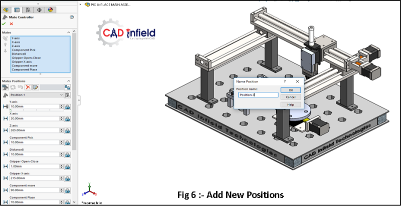
Update position
Now, similarly add position 5, 8, 11 as shown in Fig. 6,7

Refer to the following table for positions:
| Position | X-axis | Z-axis | Y-axis | Gripper Open-close | Gripper X-axis | Component Move | Component Pick | Component Place |
| 1 | 30 | 265 | 10 | 1 | 215 | 90 | 10 | 70 |
| 2 | 230 | 265 | 10 | 1 | 215 | 90 | 10 | 70 |
| 3 | 230 | 70 | 10 | 1 | 15 | 90 | 10 | 70 |
| 4 | 170 | 70 | 10 | 1 | 73 | 90 | 10 | 70 |
| 5 | 172 | 70 | 50 | 4 | 71 | 90 | 25 | 70 |
| 6 | 172 | 70 | 10 | 1 | 73 | 90 | 60 | 70 |
| 7 | 172 | 70 | 10 | 1 | 73 | 90 | 60 | 70 |
| 8 | 27 | 70 | 10 | 1 | 218 | 235 | 60 | 70 |
| 9 | 25 | 136 | 10 | 1 | 218 | 235 | 60 | 5 |
| 10 | 27 | 125 | 40 | 3.5 | 216 | 235 | 5 | 16 |
| 11 | 230 | 125 | 10 | 1 | 15 | 235 | 5 | 16 |
| 12 | 230 | 230 | 10 | 1 | 15 | 235 | 5 | 16 |
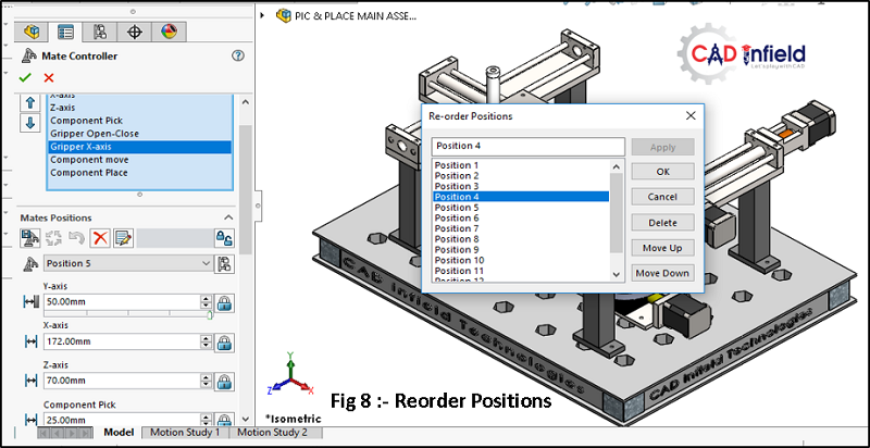
Reset, Delete and Re-order position:
Now, we have all positions saved. Next button is Reset with which we can reset the values we have assigned. Reorder button allows you to rename and delete your saved positions in its pop-up window as shown in Fig. 8.
Make all Mates Driven:
Once you enter mate controller mode, you can no longer drag your parts manually. All changes have to be done through the mate controller menu-unless you click on a specific mate’s lock button, then you unlock that part and allow it to be dragged freely by mouse cursor. If you do drag that specific part, then value in the mate controller’s menu, will grey out and gets adjusted automatically.
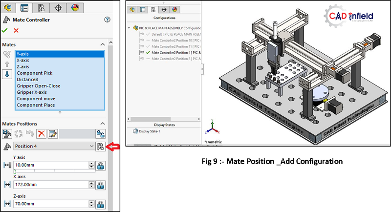
Add Configuration:
With this button, you can add different variations of your movements as shown in Fig 9 and can save the combination under a new configuration. You can find them later in the configuration manager tab as shown in Fig 9.
-
Animation:
In this option, you will find all your saved positions listed in a table with specific duration in seconds (usually 2 second on default). Click on the Calculation animation-the calculator looking button-to play your animation and see how you have done so far. If you would like to adjust a position’s speed, you can simply double click on its duration and change it. Refer Fig.10.
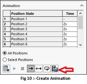 You can also choose whether you would like to play all the positions or specific range of your positions for example, position 3 or 5 only by clicking on “select position” tab.
Now, we can save the animation as an AVI file or another file format by clicking on the button shown by arrow in above Fig 10.
Conclusion:
Mate controller lets you edit specific mates that controls the degrees of freedom of your assembly. Instead of using configurations, we can use this to save different positions and create animations from them to indicate our assembly motions. So, briefly the working of assembly can be easily shown with the help of the mate controller.
This is very easy to control than Animation or motion studies as major parameter are driven through mates and position.
Created By-
For more details contact:
CAD Infield Technologies
+91- 97301 40885
Certified SOLIDWORKS Expert & CAE Professional
aatmling@cadinfield.com