- Mechanical Fundamental : Design
- Manufacturing Process Engineering
- Industrial Drawings
- Solidworks 3D
- CATIA V5 for Designers
- Design Automation
- Design Calculation
- Excel Automation and Parametric Design
- Industrial Pneumatics
- Industrial Design Practices
- Domain Exercise
- Industrial Visit
- Verbal and Non-Verbal
- Mechanical Aptitude Series
- Industrial Ethics and Behavior Management
- Resume, Tool to find por strength
- Learn from Industrial Design Automation Expert
Key Takeaways :- Introduction to Industry Vertical
- Introduction to Industry Verticals:
- Explore various industrial domains where engineering design plays a crucial role, such as aerospace, automotive, consumer goods, and manufacturing.
- Understand the specific challenges and requirements within each industry vertical and how engineering design solutions contribute to addressing them.
- Gain insights into the applications of engineering design in real-world scenarios, spanning product development, process optimization, and innovation across different sectors.
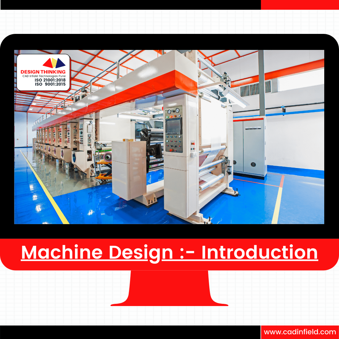
- Introduction to Machine Design Expertise:
- Learn about the role of a machine design expert in creating mechanical systems and equipment tailored to industrial needs.
- Understand the core principles of machine design, including functionality, reliability, efficiency, and safety.
- Explore the skills and knowledge required to conceptualize, design, and optimize machines for specific applications within industrial domains.
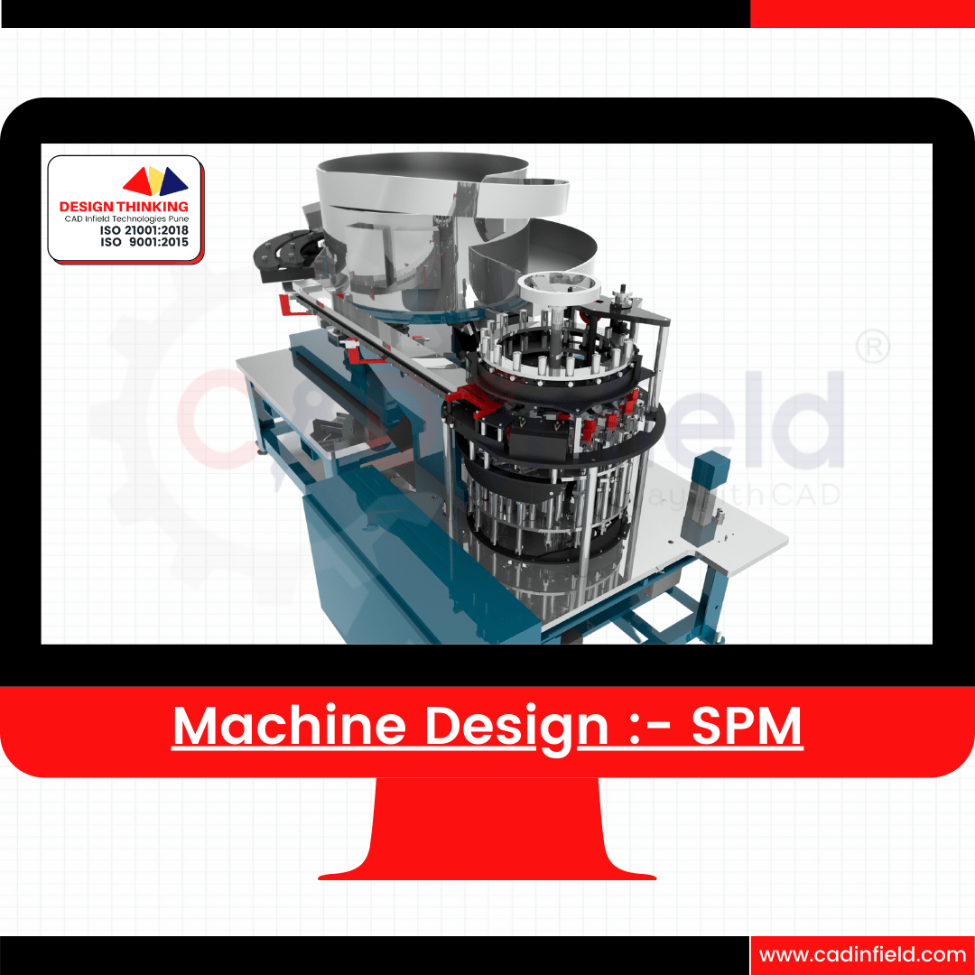
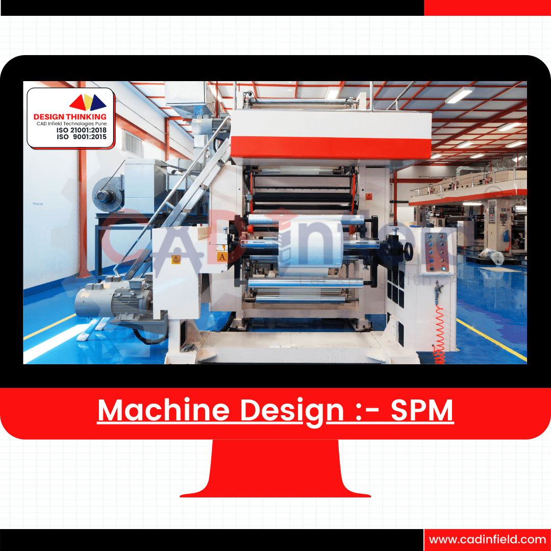
- Machine Design for Specialized Applications:
- Focus on specialized areas within machine design, such as Special Purpose Machines (SPMs) and Material Handling systems.
- Gain practical insights into designing SPMs and material handling equipment to automate industrial processes and streamline operations.
- Learn how to leverage engineering design principles and tools to develop customized solutions for unique challenges in industrial settings.
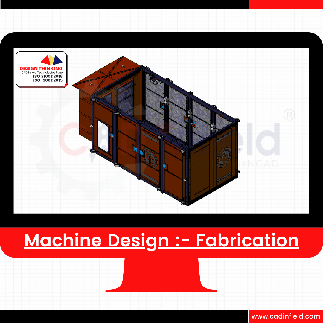
- Fabrication Design Principles:
- Dive into fabrication design, encompassing the creation of structural components, frames, and assemblies for industrial applications.
- Explore the fundamentals of fabrication design, including material selection, structural analysis, and manufacturing processes.
- Acquire skills in creating fabrication drawings, defining weldments, and optimizing designs for efficient manufacturing and assembly.
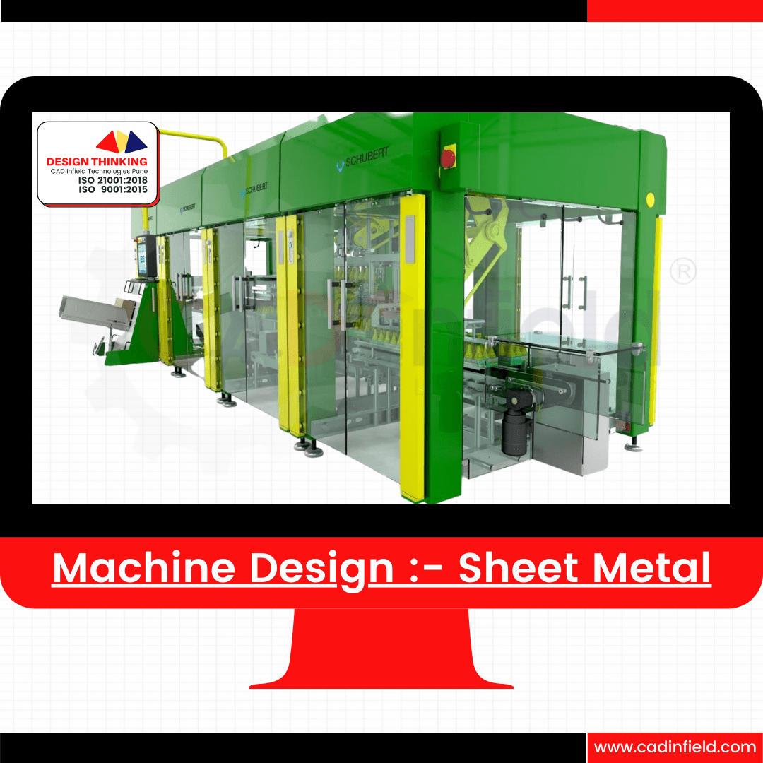
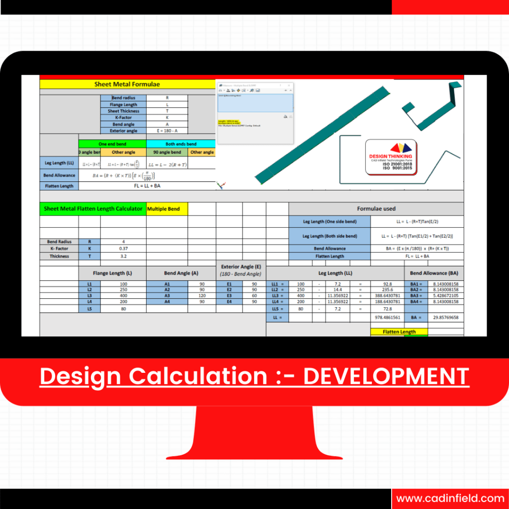
- Sheet Metal Fabrication Techniques:
- Focus on the specialized area of sheet metal fabrication, which involves shaping and forming thin metal sheets into components and assemblies.
- Learn sheet metal design techniques, including creating parts, unfolding surfaces, and generating manufacturing drawings.
- Explore best practices for designing sheet metal components that meet dimensional accuracy, strength requirements, and manufacturing feasibility.
- Delve into fixture design, which involves creating devices to support and position workpieces during manufacturing processes.
- Understand the importance of fixture design in ensuring precision, repeatability, and efficiency in manufacturing operations.
- Learn how to design fixtures tailored to specific manufacturing processes, optimizing clamping mechanisms and minimizing setup time
Industrial Learning: Why Design?
- Value Addition: Design is integral to product development, enhancing functionality, aesthetics, and user experience.
- Competitive Edge: Well-designed products stand out in the market, attracting customers and driving sales.
- Problem Solving: Design addresses user needs and challenges, offering innovative solutions to real-world problems.
- Brand Identity: Design reflects brand values and ethos, strengthening brand recognition and loyalty.
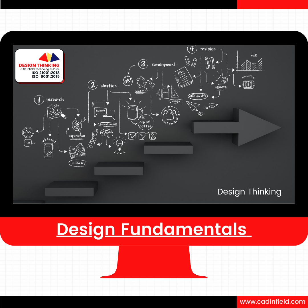
Design Fundamentals:
- Functionality: Designs should prioritize functionality, ensuring products serve their intended purpose effectively.
- Aesthetics: Aesthetic appeal enhances product attractiveness, capturing attention and fostering emotional connections.
- User-Centricity: Design with the end user in mind, considering usability, ergonomics, and user preferences.
- Sustainability: Sustainable design minimizes environmental impact, promoting eco-friendly and responsible practices.
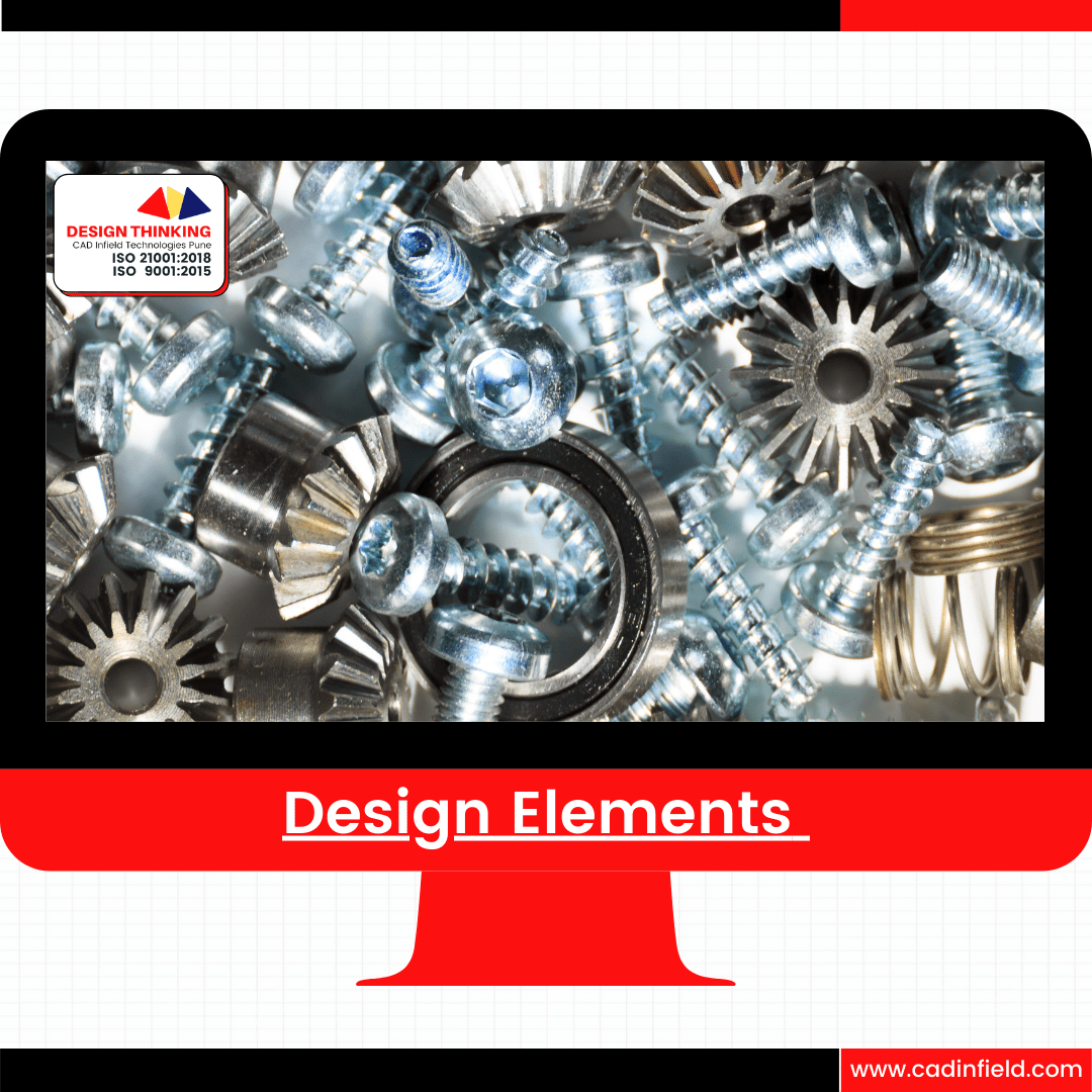
Design Elements:
- Form: Shape, structure, and visual appearance contribute to the overall design aesthetic.
- Color: Color choices influence perception, mood, and brand identity, impacting user experience.
- Texture: Surface texture adds tactile appeal and sensory interest to products.
- Typography: Typography communicates brand personality and enhances readability in design applications.
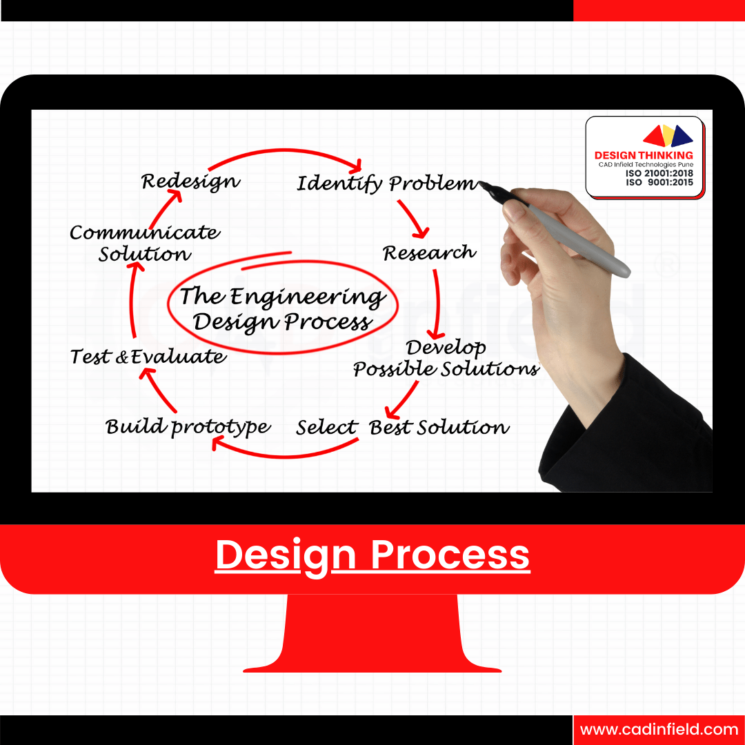
Design Process:
- Research: Understand user needs, market trends, and project requirements through research and analysis.
- Ideation: Generate creative ideas and concepts through brainstorming and sketching.
- Prototyping: Develop prototypes to test and refine design solutions, iterating based on feedback.
- Validation: Evaluate prototypes for usability, functionality, and user satisfaction, making necessary adjustments.
- Implementation: Finalize designs for production, considering manufacturing processes, materials, and cost-efficiency.
Things to Know by Designers:
- Software Proficiency: Master design software tools relevant to your industry, such as CAD, Adobe Creative Suite, or UX/UI design platforms.
- Trends and Technologies: Stay updated on emerging design trends, technologies, and best practices to remain competitive.
- Communication Skills: Effectively communicate design concepts and ideas to stakeholders, clients, and team members.
- Portfolio Development: Build a strong portfolio showcasing your design skills, projects, and achievements to potential employers.
- Continuous Learning: Cultivate a growth mindset and seek opportunities for continuous learning and skill development in the field of design
Industry 360° Spectrum

Design Fundamental
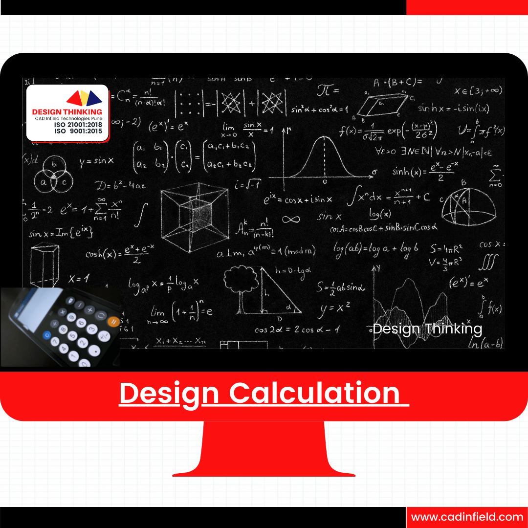
Design Calculation
Design Elements
Design Process
Machine Design
Domain Based Training :- SPM
Domain Based Training :- SPM
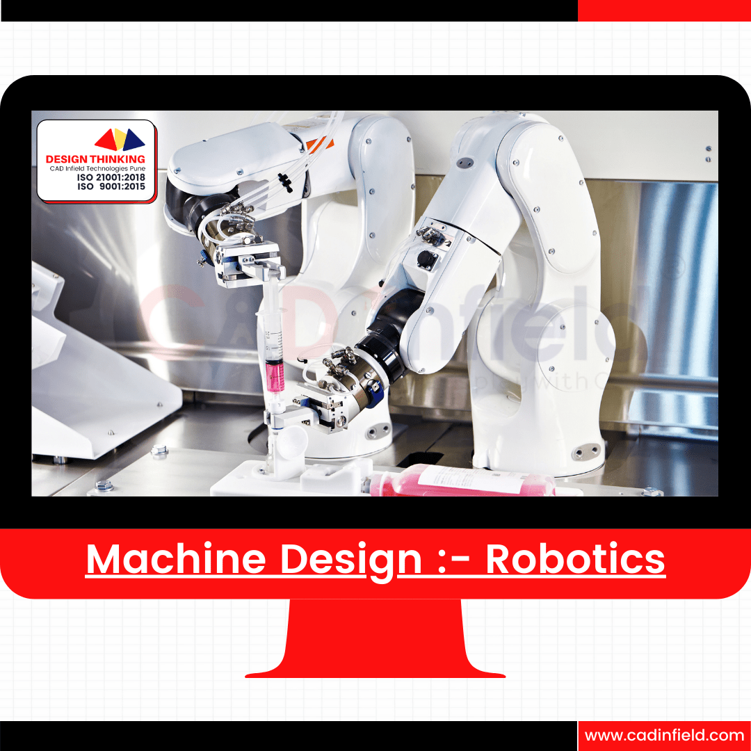
Domain Based Training :- Robotics
Domain Based Training :- Sheet Metal
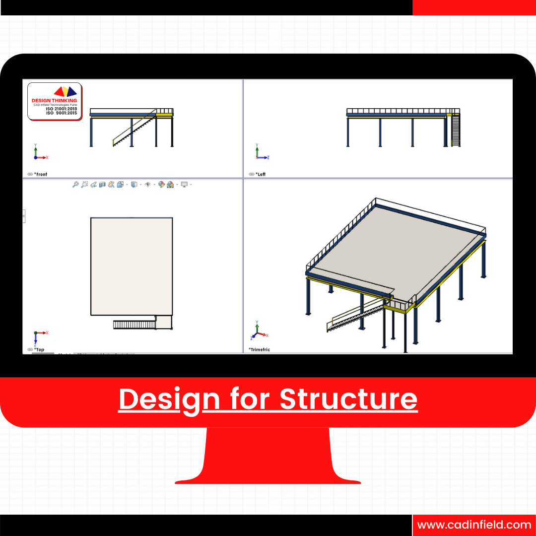
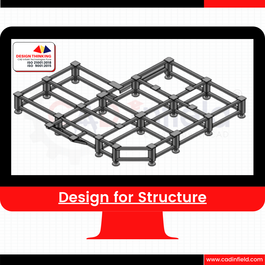
Domain Based Training :- Structure
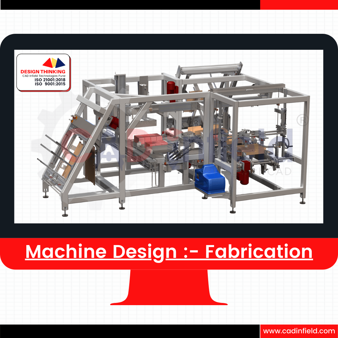
Domain Based Training :- Fabrication
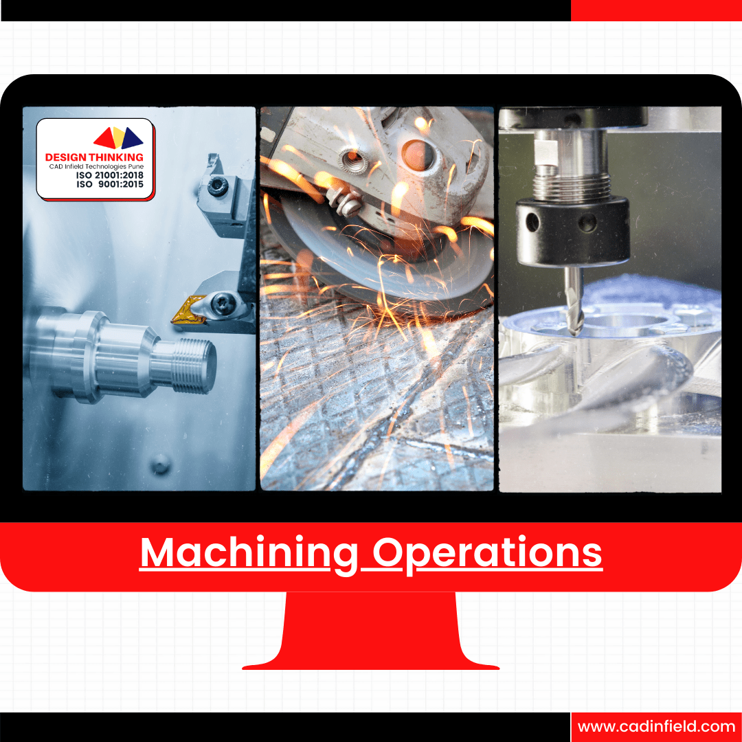
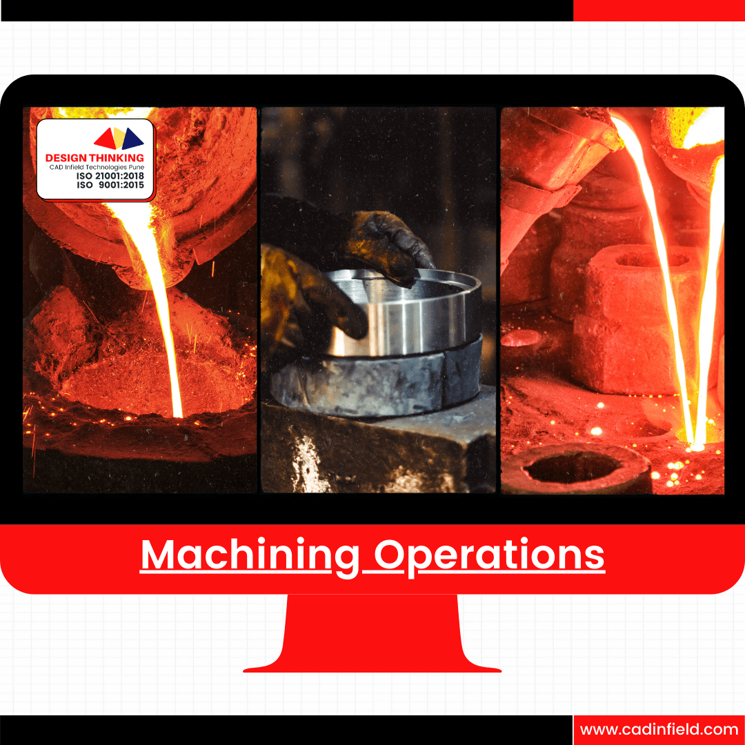
Take Away :- Machine and it's Operation
Industrial Learning:- Machining Process
Manufacturing Processes
Process Sheet
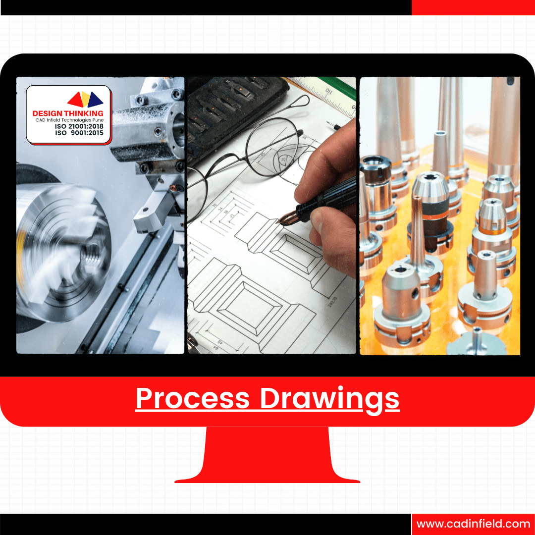
Production Methods
Key Takeaways
- Drawing Orientation:
- Understanding Standards: Learn industry standards for drawing orientation, including landscape and portrait formats.
- Clarity and Readability: Ensure drawings are oriented for clarity and readability, considering the arrangement of views and annotations.
- Consistency: Maintain consistency in drawing orientation across projects to facilitate communication and interpretation.
Sheet Format and Usages:
- Standard Formats: Familiarize yourself with standard sheet sizes such as A0, A1, A2, etc., based on ISO or local standards.
- Title Block: Include essential information in the title block, such as title, part number, revision history, and company details.
- Usage Guidelines: Understand the purpose of different sheet formats, such as assembly drawings, detail drawings, and fabrication drawings, and use them appropriately based on project requirements.
Application of Drawing:
- Communication Tool: Recognize drawings as a primary means of communication in engineering and manufacturing.
- Documentation: Use drawings to document design intent, specifications, dimensions, and tolerances for manufacturing and assembly.
- Quality Control: Drawings serve as a reference for quality control, ensuring products meet design requirements and standards.
Drawing Reading:
- Interpretation Skills: Develop the ability to interpret drawings accurately, including understanding views, dimensions, symbols, and annotations.
- Dimensioning: Understand different types of dimensions (e.g., linear, angular, radial) and their representation on drawings.
- Tolerancing: Interpret geometric dimensioning and tolerancing (GD&T) symbols to understand part tolerances and fit requirements.
Types of Drawings:
- Orthographic Views: Understand orthographic projection and how to create front, top, side, and auxiliary views to represent 3D objects on 2D drawings.
- Assembly Drawings: Create assembly drawings to show the relationship between components, their arrangement, and how they fit together.
- Detail Drawings: Provide detailed views of individual components, including dimensions, tolerances, and surface finishes.
- Fabrication Drawings: Generate drawings for fabrication and machining processes, indicating material specifications, part numbers, and machining instructions.
Industrial Learning: Fabrication Drawing
- Purpose: Fabrication drawings provide detailed instructions for fabricating structural components, frames, and assemblies.
- Components: Include views of individual parts, weld symbols, dimensions, tolerances, material specifications, and assembly instructions.
- Clarity: Ensure clarity in representation, with clear views, annotations, and detailed information for fabrication processes.
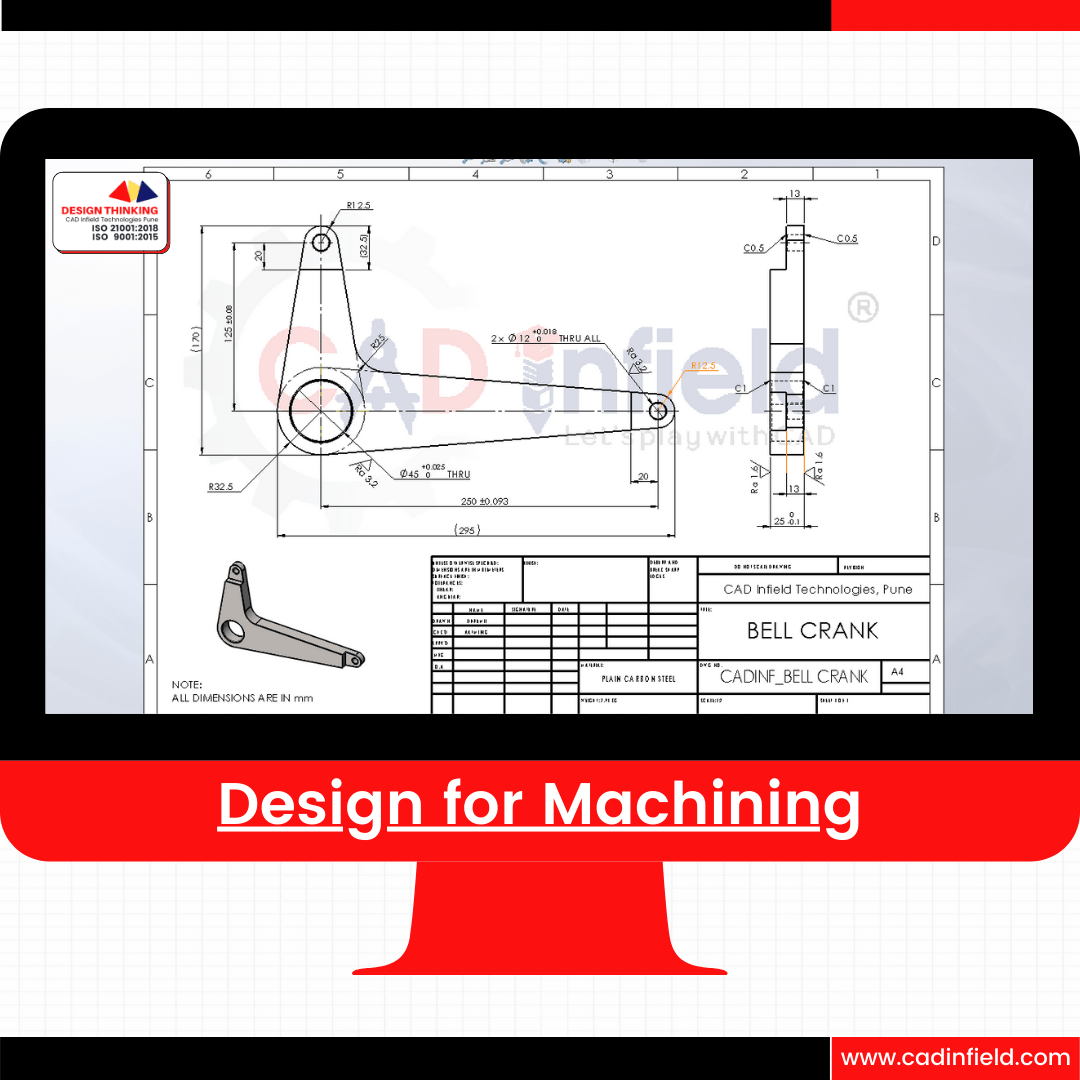
Industrial Learning: Machining Drawing
- Purpose: Machining drawings guide the manufacturing of parts through machining operations such as milling, turning, drilling, and grinding.
- Geometric Tolerances: Specify geometric tolerances, surface finishes, and machining allowances for precise part dimensions.
- Detailed Views: Provide detailed views of machined features, including hole callouts, surface profiles, and machining operations sequence.
Industrial Learning: Fixture Drawing
- Purpose: Fixture drawings depict fixtures used to hold and position workpieces during manufacturing processes, ensuring accuracy and repeatability.
- Clamping Mechanisms: Detail clamping mechanisms, locating features, and part supports for secure workpiece positioning.
- Alignment: Include alignment features and reference points to ensure proper alignment of workpieces within the fixture.
Industrial Learning: Material Handling Equipment Drawings
- Purpose: Material handling equipment drawings illustrate the design of conveyors, lifts, cranes, and other equipment used for transporting materials within industrial facilities.
- Functionality: Showcase the layout, dimensions, capacity, and operational features of material handling equipment.
- Safety Considerations: Incorporate safety features, such as guards, sensors, and emergency stops, to ensure safe operation.
Industrial Learning: Automation System Drawings
- Purpose: Automation system drawings detail the design of automated machinery and systems for streamlining manufacturing processes.
- Control Systems: Include schematics of control panels, electrical wiring diagrams, and programmable logic controller (PLC) layouts for automation control.
- Integration: Illustrate how automated components such as sensors, actuators, and robotic arms are integrated into the overall system.
Industrial Learning: Plastic Component Drawings
- Purpose: Plastic component drawings represent the design of injection-molded or thermoformed plastic parts used in various industrial applications.
- Wall Thickness: Specify uniform wall thickness, draft angles, and gating locations to ensure moldability and structural integrity.
- Material Properties: Detail material specifications, including plastic type, color, and surface finish requirements.
- Parting Lines: Define parting lines, ejector pin locations, and other mold features necessary for manufacturing plastic components.
Industrial Learning: Process Drawings
- Purpose: Process drawings depict manufacturing processes such as welding, casting, forging, or heat treatment.
- Sequence: Illustrate the step-by-step process flow, including setup, operations, and quality checks.
- Parameters: Specify process parameters such as temperature, pressure, and duration for each stage of the manufacturing process.
Industrial Learning: Laser Cutting Drawings
- Purpose: Laser cutting drawings detail the design of parts or components to be cut using laser technology.
- Geometry: Specify the geometry of cut features, including profiles, holes, and internal cutouts.
- Tolerances: Define tolerances for laser cutting accuracy, ensuring precise dimensions and fit.
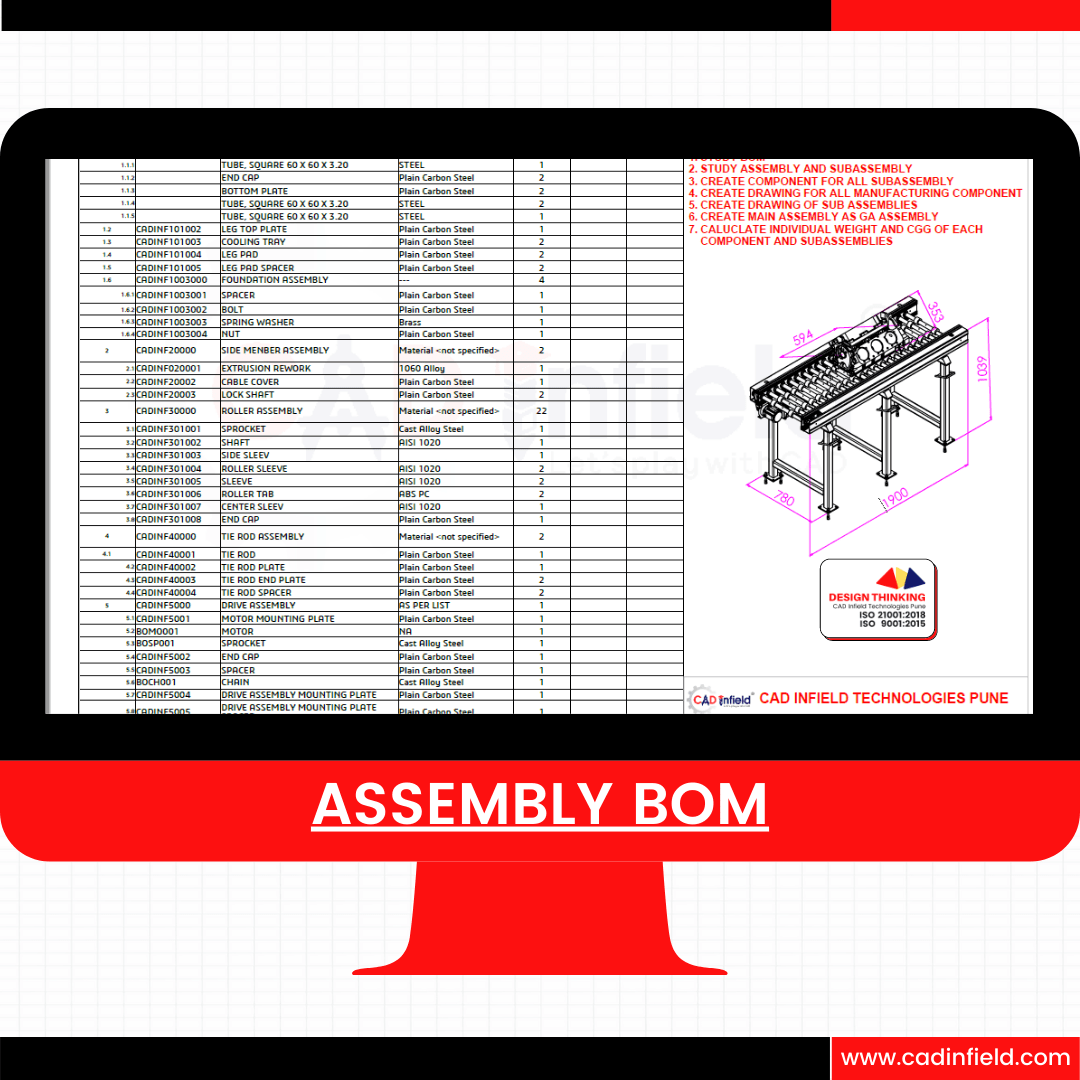
Industrial Learning: Assembly Drawings
- Purpose: Assembly drawings provide instructions for assembling multiple components into a finished product.
- Exploded Views: Include exploded views to illustrate the relationship between components and their assembly sequence.
- Bills of Materials: List all components and parts required for assembly, including part numbers, quantities, and descriptions.
Machining Drawing

Machining Drawing
Assembly BOM
Sub-Assembly Drawing
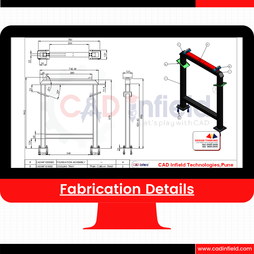
Fabrication Drawing
Fabrication Drawing
Sheet Metal Drawing Details
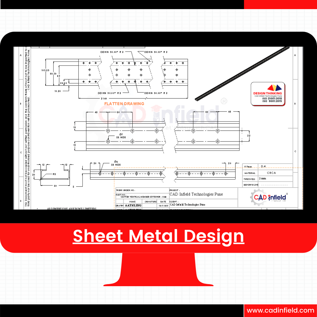
Sheet Metal Drawing Details

Machine Design Components
Introduction to Machine Design, SOLIDWORKS Basics and the User Interface, Introduction to Sketching, Basic Part Modeling Symmetry and Draft, Patterning.Revolved Features, Shelling and Ribs,Editing: Repairs, Editing: Design Changes, Configurations for Part Creation
50 plus Machine Design Component for Level 0 to Level 1( Basic to Advance)
Complex Design Component
Multi-body Design Techniques,Saving Solid Bodies, Sketching with Splines, Introduction to Sweeping.Working with Curves, Advanced Sweeping. Boundary Feature and Lofting
Assembly Design
Advanced Mate Techniques, Top Down Assembly Modeling, Assembly Features, Smart Fasteners and Smart Components, Assembly Editing.Using Configurations with Design, Large Assemblies Assemblies, Layout-based Assembly
Linear Static Analysis :- FEA
Linear Static Analysis, Stress Concentration, Geometry Simplification, Mesh,Post Processing, Singularity, Convergence, Solid or Tetrahedral Mesh Shell or Triangular Mesh , Beam Mesh Von Mises Stress and Principle Stress and Strain
Complex Structural and Fabrication Design
Structure & Fabrication Design, Cut List, Multibody, Fabrication Drawing 2D & 3D Sketch and Weldment
Design for Manufacturing
Drawing Sheets and Views,Dimension, Annotations, Assembly Drawing Views, Sheet Formats and Templates, Bill of Materials and Tables, Drawing References and Comparison
Animation and Robotic Simulation
Introduction to Animation, Basic Motion Time Based Motion, Animation Wizard Use off Gravity, Motor, Spring, Contact and Boundary Conditions
Sheet Metal and Fabrication Design
Sheet Metal Flange Method. Sheet Metal Parts Sheet Metal Convert Method Multi-body Forming Tool Additional Sheet


CATIA V5 for Designers
Course Description:
This course provides an introduction to CATIA, a leading CAD software widely used in engineering design and manufacturing industries. Students will learn fundamental concepts and practical skills necessary for creating 3D models, assemblies, and drawings using CATIA software. Emphasis will be placed on hands-on exercises and real-world applications.
A syllabus for a CATIA course for design engineers would typically cover a range of topics related to CAD (Computer-Aided Design) software, specifically focusing on CATIA. Here’s a sample syllabus that outlines the key areas to be covered:
Course Title: CATIA for Design Engineers
Course Description: This course provides an introduction to CATIA, a leading CAD software widely used in engineering design and manufacturing industries. Students will learn fundamental concepts and practical skills necessary for creating 3D models, assemblies, and drawings using CATIA software. Emphasis will be placed on hands-on exercises and real-world applications.
Course Objectives:
- Understand the basic principles of CAD and CATIA software.
- Develop proficiency in creating 3D models and assemblies.
- Gain skills in generating engineering drawings and documentation.
- Apply CATIA tools and techniques to solve engineering design problems.
- Enhance problem-solving abilities through practical design projects.
Prerequisites: Basic understanding of engineering design principles and familiarity with computer usage.
Course Outline:
- Introduction to CATIA:
- Overview of CAD software: Understand the historical context and evolution of CAD software, ranging from early 2D drafting tools to modern 3D modeling suites. Explore the various types of CAD software available, including parametric modeling, direct modeling, and hybrid modeling approaches. Discuss the significance of CAD software in accelerating the design process, improving accuracy, and facilitating collaboration.
- Introduction to CATIA interface and navigation: Provide an in-depth tour of CATIA’s user interface, covering elements such as the menu bar, toolbar, specification tree, workbench selector, and command windows. Explain the purpose and functionality of each interface component, emphasizing efficient navigation techniques to streamline workflow and maximize productivity.
- Understanding the part design workbench: Delve into the Part Design workbench, which serves as the primary environment for creating 3D solid models in CATIA. Explore the concept of parametric modeling, where geometry is defined by dimensions, constraints, and relationships. Demonstrate how to create sketches, apply constraints, and extrude features to generate solid geometry. Discuss best practices for organizing features and managing design history within the part design environment.
- Sketcher Module:
- Creating 2D sketches: Explore the fundamentals of sketching, emphasizing precision and accuracy in sketch creation. Discuss sketching techniques, including point, line, circle, arc, spline, and ellipse creation. Demonstrate strategies for controlling sketch geometry using constraints, dimensions, and geometric relationships. Illustrate advanced sketching features such as offset, trim, extend, and mirror for more complex sketching tasks.
- Sketch constraints and dimensions: Provide a comprehensive overview of sketch constraints, categorizing them into dimensional constraints (e.g., length, angle, radius) and geometric constraints (e.g., coincident, parallel, tangent). Explain how constraints maintain design intent and facilitate parametric modeling by establishing relationships between sketch elements. Showcase dimensioning techniques for specifying exact measurements and tolerances within sketches.
- Sketch-based features: Introduce sketch-based features as a powerful method for creating 3D geometry from 2D sketches. Cover essential features such as extrude, revolve, sweep, and blend, demonstrating how to leverage sketches to generate complex solid shapes. Illustrate the versatility of sketch-based features for rapid prototyping, design exploration, and parametric modeling.
- Part Design Module:
- Creating solid models from sketches: Deepen understanding of solid modeling principles by transitioning from sketches to 3D geometry. Guide students through the process of creating solid features using sketch-based techniques, emphasizing the importance of design intent and feature hierarchy. Showcase advanced feature creation methods, including draft, rib, shell, and hole creation, to accommodate diverse design requirements.
- Editing and modifying features: Explore strategies for modifying existing features to refine design geometry or accommodate design changes. Cover feature editing operations such as fillet, chamfer, mirror, and split, enabling students to manipulate geometry while preserving model integrity. Discuss the implications of feature dependencies and feature order on design flexibility and parametric control.
- Advanced modeling techniques: Introduce advanced modeling tools and workflows for tackling complex design challenges. Highlight techniques such as multi-body modeling, pattern replication, and feature mirroring for efficient design iteration and optimization. Address strategies for managing complex geometry, optimizing feature performance, and maintaining model robustness in large-scale projects.
- Assembly Design Module:
- Creating assemblies: Provide a comprehensive overview of assembly design principles, focusing on the assembly structure, component relationships, and assembly behavior. Guide students through the process of creating assemblies by inserting, positioning, and constraining components within the assembly environment. Emphasize assembly layout strategies, component naming conventions, and assembly organization techniques for clarity and efficiency.
- Constraints and mates: Deep dive into assembly constraints and mates as the foundation for establishing component relationships and motion behavior within assemblies. Cover a wide range of constraint types, including coincident, distance, angle, and tangent constraints, to enforce assembly geometry and simulate real-world interactions. Discuss best practices for constraint selection, constraint visualization, and constraint management in complex assemblies.
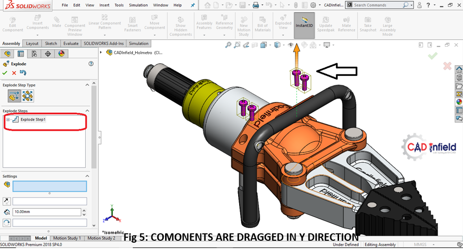
- Exploded views and assembly animations: Explore techniques for visualizing and communicating assembly sequences, part relationships, and motion paths through exploded views and animations. Demonstrate how to create exploded views to illustrate component assembly/disassembly procedures, highlighting key components and their spatial relationships. Introduce animation tools for animating assembly motion, including component translation, rotation, and inter-part motion, to enhance design communication and presentation.
- Drafting Module:
- Creating engineering drawings: Dive into the principles of engineering drawing creation, covering essential elements such as views, dimensions, annotations, and symbols. Guide students through the process of creating 2D engineering drawings from 3D models, emphasizing the projection method, view layout, and drawing standards compliance. Discuss drawing templates, title blocks, and sheet formats for standardized documentation.
- Dimensioning and annotations: Explore dimensioning techniques for communicating geometric characteristics, tolerances, and fit requirements on engineering drawings. Cover dimension types (e.g., linear, angular, radial), dimension placement strategies, and dimensioning standards (e.g., ASME Y14.5) to ensure clarity and accuracy in dimension representation. Introduce annotation tools for adding text, symbols, surface finish symbols, and other annotations to convey additional design information.
- Bill of Materials (BOM) generation: Provide hands-on experience in generating bills of materials (BOMs) directly from assembly models, automating the extraction of component information for documentation and procurement purposes. Discuss BOM formats, item numbering schemes, and BOM organization conventions to facilitate assembly understanding, part identification, and inventory management.
- Surface Design Module (Optional):
- Introduction to surface modeling: Explore the principles of surface modeling as an essential complement to solid modeling for creating complex, organic shapes. Introduce surface creation techniques such as lofting, sweeping, and blending, emphasizing continuity, curvature, and surface quality. Discuss the advantages of surface modeling for achieving aesthetic, ergonomic, and aerodynamic design objectives.
- Advanced surface creation techniques: Delve deeper into advanced surface modeling workflows for addressing challenging design requirements. Cover topics such as curvature analysis, surface curvature manipulation, and surface refinement techniques for achieving smooth, continuous surfaces with precise geometric control. Showcase real-world applications of advanced surface modeling in industries such as automotive design, consumer products, and aerospace engineering.
- Generative Shape Design Module (Optional):
- Introduction to advanced surface modeling: Introduce the Generative Shape Design module as a specialized environment for creating complex freeform surfaces and sculptural forms. Discuss the underlying principles of freeform surface modeling, including control point manipulation, curve networks, and surface continuity. Showcase examples of freeform surface design in product styling, industrial design, and architectural modeling.
- Freeform surface creation and manipulation: Provide hands-on experience in creating and manipulating freeform surfaces using a variety of tools and techniques. Cover surface creation methods such as spline-based modeling, surface skinning, and surface stitching for achieving desired surface forms. Explore advanced surface manipulation techniques such as curvature matching, surface blending, and surface analysis to refine surface aesthetics and ensure design integrity.
Benefits of Learning CATIA:
- Career Opportunities: CATIA skills are highly sought after in industries such as aerospace, automotive, and manufacturing. By mastering CATIA, you’ll open doors to exciting career opportunities in these fields.
- Design Efficiency: CATIA streamlines the design process, allowing you to create complex models and assemblies with ease. Its parametric modeling capabilities make it easy to iterate designs and make changes on the fly.
- Collaboration: CATIA facilitates collaboration among design teams, enabling seamless sharing of models and documentation. This fosters teamwork and ensures everyone is on the same page throughout the design process.
- Professional Development: Learning CATIA demonstrates your commitment to professional development and lifelong learning. It’s a valuable skill that will set you apart in the competitive job market and help you advance in your career.
Conclusion:
In this CATIA course, you’ll gain practical skills that are in high demand in today’s engineering and design industries. Whether you’re a student looking to kickstart your career or a professional seeking to enhance your skill set, mastering CATIA will open up a world of possibilities for you. Get ready to unleash your creativity and bring your design ideas to life with CATIA!
Benefits of Design Automation
-
- No dependency on programmers or implementers –
Excel is readily configurable by mechanical engineers having no programming or IT systems knowledge.
-
- Flexible template-based approach, avoids any programming –
Based on our experience in providing design automation applications for many customers we created a flexible template based tool which converts your rules and linkage information into readymade applications.
-
- Common repository of rules –
Excel have common variable table which includes design calculations, validations, selection rules. This enables complete control over design logic at one place.
-
- Flexibility of modeling approach –
Use master models, building blocks like library components, features. No need of separate models to be created for configurator approach.
-
- Easy Integration with ERP systems –
CSV transaction file is a accessible for search / append / edit from ERP system.


Design Automation Gateway
1.Design table – SOLIDWORKS have design table for individual parts & we can enhance design table to multi part assembly design table.
2.Excel automation – SOLIDWORKS have integrated spreadsheet for calculating & validating variables. you can define variables in spreadsheet format.
3.Equations – In SolidWorks you have to define equations in Model itself. you can define, modify and execute equations outside the model for better performance.
4.Master modeling – Allows to modify parameters of multiple parts through common application.
5.Configurations – Allows use required configurations through common application.
6.Library components and features – You can create required geometry with rules by accessing SolidWorks design library using building blocks.
7.Custom properties – Tab Builder custom properties to specifications and design outputs for comprehensive ERP integration.
Key Takeaways: Design Calculations and Catalog Selection for Machine Elements
- Understanding Machine Elements:
- Current Industrial Need: Industries demand efficient, reliable, and sustainable machine elements to optimize operations and reduce environmental impact.
- Consideration: Incorporate advanced materials and manufacturing techniques while adhering to industry standards to enhance performance and longevity.
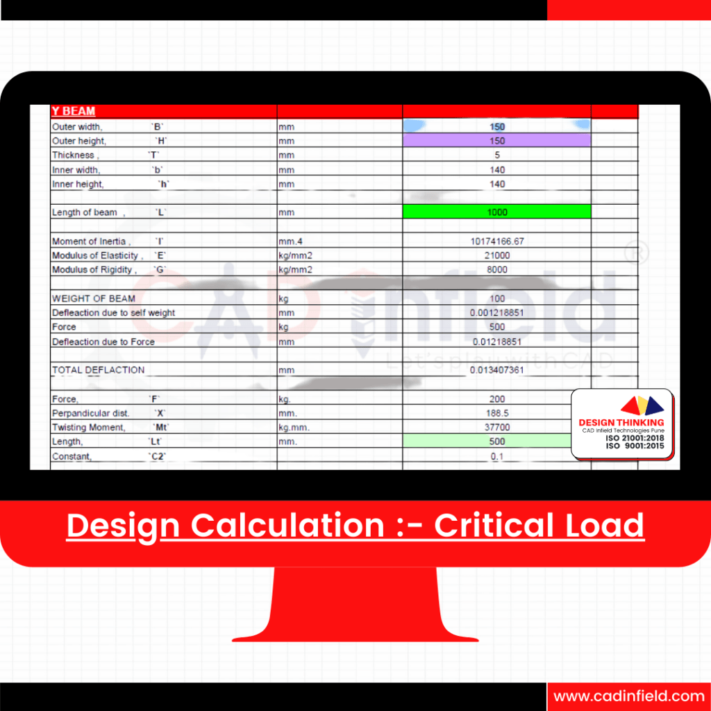
- Design Calculation Fundamentals:
- Current Industrial Need: With Industry 4.0, there’s a need for predictive maintenance and real-time monitoring. Design calculations should integrate sensor data and analytics for optimized performance.
- Consideration: Utilize simulation tools for virtual testing, enabling rapid iteration and cost-effective design optimization.
- Bearing Calculation:
- Current Industrial Need: Bearings must withstand high loads and speeds with minimal maintenance. Advanced lubrication systems and sealing mechanisms enhance reliability.
- Consideration: Select bearings from catalogs with detailed performance data and reliability metrics, ensuring compatibility with application requirements.
- Coupling Calculation:
- Current Industrial Need: High torsional stiffness and precision are crucial for automation and robotics. Flexible couplings with damping properties mitigate vibration.
- Consideration: Choose couplings from catalogs offering a range of options, considering factors such as torque capacity, misalignment tolerance, and damping characteristics.
- Bolt Calculation:
- Current Industrial Need: Bolts must provide secure joints in harsh environments. Corrosion-resistant coatings and materials ensure longevity and performance.
- Consideration: Select bolts from catalogs with corrosion resistance data and material specifications, ensuring compatibility with environmental conditions.
- Torque Calculation:
- Current Industrial Need: Compact, efficient motors and gearboxes are vital for EVs and renewable energy systems. Regenerative braking and variable-speed drives optimize energy usage.
- Consideration: Choose motors and gearboxes from catalogs with efficiency ratings and performance curves, facilitating accurate torque calculations.
- Drive Calculation:
- Current Industrial Need: Precise control and scalability are essential for varying production demands. Modular drive solutions with IoT integration enable data-driven decision-making.
- Consideration: Select drives from catalogs with compatibility information and communication protocols, ensuring seamless integration with existing systems.
- Motor and Gearbox Selection:
- Current Industrial Need: High power density and reliability support advanced motion control applications. BLDC motors and planetary gearboxes optimize performance and energy consumption.
- Consideration: Choose motors and gearboxes from catalogs with detailed specifications and CAD models, facilitating accurate selection and integration into designs.
- Belt Design:
- Current Industrial Need: Belts are critical for power transmission in various industrial applications. Optimal belt design ensures efficient power transfer and minimal wear.
- Consideration: Utilize design software and catalogs to select belts with appropriate size, profile, and material properties, considering factors such as load capacity, speed, and environmental conditions.
- Chain Selection:
- Current Industrial Need: Chains are essential for transmitting power and motion in heavy-duty applications such as mining, agriculture, and material handling.
- Consideration: Choose chains from catalogs with detailed specifications, including pitch, roller diameter, tensile strength, and corrosion resistance, ensuring compatibility with load requirements and operating conditions.
- Catalog Selection:
- Current Industrial Need: Access to comprehensive catalogs with detailed component information streamlines design and procurement processes.
- Consideration: Utilize catalogs from reputable suppliers with real-time inventory updates and online configurators for rapid prototyping and design iterations.
- Hardware Selection:
- Current Industrial Need: Quality hardware components are critical for product reliability and safety. RFID or QR code-based tracking systems ensure traceability throughout the supply chain.
- Consideration: Source hardware from catalogs with quality assurance certifications and traceability features, ensuring compliance with industry standards.
- Pneumatic Component Selection:
- Current Industrial Need: Quick response times and precise control support flexible manufacturing. Smart pneumatic components enable real-time monitoring and optimization.
- Consideration: Choose pneumatic components from catalogs with compatibility information and performance data, ensuring seamless integration and efficient operation.
- Circlip Selection:
- Current Industrial Need: High-strength circlips are essential for securing components in demanding applications. Choose from catalogs with material specifications and performance data.
- Consideration: Select circlips with detailed specifications from catalogs offering a range of options, ensuring compatibility with shaft diameter and groove dimensions.
Any many more ……
- Comprehensive Catalogs (100+ Varity of Catalogue):
- Importance: Wide selection range for tailored solutions.
- Efficiency: Streamlines design process, offers flexibility.
- Integration: Complements design data handbooks.
- Design Data Handbooks:
- Supplementary Resource: Provides technical information and standards.
- Validation: Validates catalog specifications and regulatory compliance.
- Educational Tool: Enhances understanding and training.
- Hand Calculations:
- Validation Tool: Assesses suitability and customizes design parameters.
- Risk Mitigation: Verifies theoretical predictions, ensures safety margins.
- Educational Tool: Develops problem-solving skills and deepens understanding.
- Correlation between Theoretical and Practical Calculations:
- Quality Assurance: Ensures consistency and reliability in design.
- Continuous Improvement: Drives innovation and optimization through feedback loop.
- Efficiency: Minimizes design iterations, enhances engineering excellence.


- Efficiency in Design Iterations:
- Automation streamlines iterative design processes, reducing time and effort spent on manual adjustments.
- It accelerates design cycles, enabling rapid prototyping and faster product development.
- Engineers can quickly test and refine design variations to optimize performance and meet specifications.
- Customization for Specific Applications:
- Automation allows for rapid customization of equipment to suit diverse industry needs and unique application requirements.
- Engineers can easily adapt designs to accommodate different materials, processes, and operational environments.
- Customized automation equipment enhances productivity, efficiency, and safety in various industrial settings.
- Standardization and Consistency:
- Automated design processes ensure consistency and adherence to industry standards across equipment designs.
- Standardized design elements and components minimize errors and improve reliability in automated systems.
- Consistent designs facilitate maintenance, repair, and replacement, reducing downtime and operational disruptions.
- Parametric Design Flexibility:
- Parametric modeling enables engineers to create flexible designs with customizable dimensions, configurations, and functionalities.
- Automation tools adjust design parameters automatically based on input criteria, facilitating rapid design changes and adaptations.
- Parametric flexibility enhances design versatility and enables quick response to evolving customer needs and market trends.
- Integration with Manufacturing Processes:
- Automated equipment designs seamlessly integrate with manufacturing processes, ensuring compatibility with fabrication and assembly systems.
- Direct transfer of design data to production systems reduces lead times and minimizes errors in manufacturing.
- Integrated design-to-manufacturing workflows optimize production efficiency and enhance overall operational performance.
- Cost Reduction and Optimization:
- Design automation minimizes engineering costs by streamlining design processes, reducing manual labor, and optimizing resource utilization.
- Optimization algorithms identify cost-saving opportunities and efficiency improvements, maximizing return on investment.
- Automated design workflows minimize material waste, optimize energy consumption, and reduce overall lifecycle costs of automation equipment.
- Scalability and Reusability:
- Automated equipment designs are easily scalable to accommodate changes in production requirements, market demand, or technological advancements.
- Design elements and configurations can be reused across multiple projects, saving time and resources in design development.
- Scalable and reusable designs enhance agility and adaptability, enabling organizations to respond quickly to changing business needs and market conditions.
- Collaboration and Communication:
- Automated design tools facilitate collaboration among multidisciplinary teams by providing a standardized platform for sharing design data and feedback.
- Cloud-based collaboration platforms enable real-time collaboration, allowing team members to work together seamlessly regardless of geographic location.
- Improved communication and coordination foster innovation, knowledge sharing, and cross-functional teamwork, leading to more successful automation projects and enhanced business outcomes.
- Pneumatic Circuit Design Training SyllabusModule 1: Introduction to Pneumatics
- Overview of pneumatics and its applications in various industries
- Basic principles of pneumatics: pressure, flow, and force
- Comparison between pneumatic and hydraulic systems
- Safety considerations in pneumatic system design and operation
Module 2: Pneumatic Components and Symbols
- Overview of common pneumatic components: compressors, cylinders, valves, filters, regulators, and actuators
- Identification and interpretation of pneumatic symbols in circuit diagrams
- Functionality and operation principles of different pneumatic components
- Selection criteria for pneumatic components based on application requirements
Module 3: Pneumatic Circuit Basics
- Understanding pneumatic circuit diagrams: symbols, lines, and annotations
- Introduction to pneumatic circuit design principles: series, parallel, and combination circuits
- Types of pneumatic circuits: control circuits, sequencing circuits, and safety circuits
- Hands-on exercises on interpreting and analyzing pneumatic circuit diagrams
Module 4: Control Valves and Actuators
- Types of pneumatic control valves: directional control valves, flow control valves, pressure control valves, and shuttle valves
- Selection criteria for control valves based on application requirements
- Overview of pneumatic actuators: cylinders, rotary actuators, and grippers
- Hands-on exercises on sizing and selecting control valves and actuators for specific applications
Module 5: Pneumatic Circuit Design Techniques
- Design considerations for efficient pneumatic circuits: pressure drop, flow control, and energy conservation
- Strategies for minimizing air consumption and optimizing system performance
- Troubleshooting techniques for identifying and resolving pneumatic circuit issues
- Case studies and real-world examples of pneumatic circuit design projects
Module 6: Advanced Pneumatic Circuit Design
- Introduction to advanced pneumatic components: proportional valves, servo-pneumatic systems, and pneumatic logic controls
- Integration of sensors and feedback devices in pneumatic systems for closed-loop control
- Designing complex pneumatic circuits for specific industrial applications
- Simulation and modeling of pneumatic circuits using software tools
Module 7: Practical Applications and Projects
- Hands-on laboratory sessions to apply pneumatic circuit design principles in practical scenarios
- Design and implementation of pneumatic circuits for specific tasks and applications
- Project-based learning activities to design, build, and test pneumatic systems
- Presentation and review of student projects to demonstrate understanding and proficiency in pneumatic circuit design
Module 8: Industry Standards and Best Practices
- Overview of industry standards and regulations governing pneumatic system design and operation
- Best practices for designing safe, efficient, and reliable pneumatic circuits
- Emerging trends and technologies in pneumatic system design and automation
- Career opportunities and professional development pathways in the field of pneumatic circuit design
The benefits for mechanical engineering freshers learning about pneumatic circuit design in brief:
-
- Practical Skills: Develop hands-on experience in designing and implementing pneumatic systems.
- Industry Relevance: Gain knowledge applicable across various sectors like manufacturing and automation.
- Problem-Solving: Enhance problem-solving abilities through system analysis and troubleshooting.
- Integration: Understand how pneumatic systems integrate with automation and control systems.
- Career Opportunities: Increase employability in fields such as mechanical design and maintenance engineering.
- Foundational Knowledge: Build a solid foundation for further learning in fluid power engineering and related fields.
Data & File Management
- Certainly! Here’s a concise overview of file management features in SOLIDWORKS and their industrial usages:
- File Management:
- SOLIDWORKS provides robust file management capabilities to organize, store, and manage design files efficiently.
- Engineers can create folders, subfolders, and categories to structure design data logically and facilitate easy access and retrieval.
- File management tools help prevent data loss, version control issues, and duplicate files by providing automated revision control and file naming conventions.
- Pack & Go:
- The Pack & Go feature in SOLIDWORKS allows users to quickly package and transfer design files, including parts, assemblies, drawings, and associated documents, to a new location.
- It ensures that all referenced files, configurations, and dependencies are included, maintaining file integrity and eliminating missing file errors.
- Pack & Go simplifies tasks such as sharing designs with collaborators, archiving projects, and preparing files for manufacturing or assembly.
- Reference Management:
- SOLIDWORKS enables efficient management of references between parts, assemblies, and drawings to maintain design integrity and update dependencies automatically.
- Engineers can establish parent-child relationships, mate references, and external references to ensure that changes in one component propagate correctly throughout the assembly.
- Reference management tools minimize errors, reduce rework, and improve collaboration among team members working on complex design projects.
- Basic PDM (Product Data Management):
- SOLIDWORKS offers basic PDM functionality to manage design data, control access, and track revisions within a centralized database.
- Basic PDM allows users to check files in and out, track file history, and enforce user permissions to prevent unauthorized modifications.
- It provides a simple yet effective solution for small to medium-sized teams to organize and collaborate on design projects effectively.
- Industrial Usages:
- In industries such as aerospace, automotive, and consumer goods, efficient file management is essential for organizing large volumes of design data, ensuring compliance with industry standards, and meeting project deadlines.
- Pack & Go simplifies the process of sharing design files with suppliers, subcontractors, and manufacturing partners, ensuring that all necessary files and dependencies are included.
- Reference management tools are crucial for complex assemblies with multiple components, allowing engineers to maintain design intent and minimize errors during design changes.
- Basic PDM systems provide a cost-effective solution for smaller organizations or departments to manage design data securely, enforce version control, and streamline collaboration processes.
In summary, SOLIDWORKS’ file management features, including Pack & Go, reference management, and basic PDM, play a vital role in ensuring efficient design data organization, collaboration, and integrity across various industries. These tools help streamline design workflows, minimize errors, and improve productivity for engineering teams working on complex projects.
- File Management:
Large Assembly Handling
Let’s discuss the tools and techniques in SOLIDWORKS for managing large assemblies, simplified assembly techniques, and the use of SpeedPak and standardization:
- Tools and Techniques for Large Assemblies:
- Assembly Structure: Organize the assembly structure logically with subassemblies, grouping related components together to simplify navigation and improve performance.
- Component Suppression: Use component suppression to temporarily hide or exclude unnecessary components from the assembly to reduce computational load and enhance performance.
- Lightweight Components: Convert large or complex components into lightweight representations to reduce memory usage and improve responsiveness while preserving visual fidelity.
- Level of Detail (LOD): Implement different levels of detail for components within the assembly, allowing users to switch between simplified representations and fully detailed models based on their requirements.
- Assembly Visualization: Utilize assembly visualization tools to analyze and optimize assembly performance by identifying and addressing components that contribute most to computational overhead.
- Simplified Assembly Techniques:
- Top-Down Design: Employ top-down design methodologies to create simplified assembly structures, starting with defining overall system architecture and gradually adding detail to individual components.
- Skeleton Models: Utilize skeleton models or master sketches to define key geometry and relationships within the assembly, providing a reference for creating and positioning components accurately.
- Smart Mates: Use smart mates and assembly features like mate references to automate the placement and alignment of components, reducing manual effort and ensuring consistent assembly configurations.
- Configurations: Leverage configurations to create multiple variations of assemblies with different component arrangements, simplifying design exploration and accommodating different design scenarios or product variants.
- Subassembly Design: Break down complex assemblies into smaller, manageable subassemblies, each representing a functional or modular unit, facilitating parallel development and easier troubleshooting.
- SpeedPak and Standardization:
- SpeedPak: Use SpeedPak configurations to create simplified representations of assemblies optimized for performance without sacrificing visual clarity. SpeedPak reduces computational overhead by capturing only essential geometry required for visualization and basic analysis.
- Standardization: Establish standardized design practices and templates for creating and managing assemblies to ensure consistency and efficiency across projects. Standardization includes naming conventions, assembly structures, mate types, and component libraries, streamlining design workflows and collaboration.
By implementing these tools and techniques in SOLIDWORKS, users can effectively manage large assemblies, simplify assembly processes, and leverage features like SpeedPak and standardization to optimize performance and productivity while maintaining design integrity.
- Concept Design
- Material Handling
- Fixture Design
- Basic Mold Design
Including knowledge related to manufacturing materials in industrial visits enhances students’ understanding of the entire production process. Here’s how it contributes to the objectives of an industrial visit:
- Insight into Design and Manufacturing Processes:
- Understanding manufacturing materials provides students with insights into how material properties influence the design and manufacturing processes.
- Students learn about the selection criteria for different materials based on their mechanical properties, durability, cost-effectiveness, and suitability for specific applications.
- Observing the use of various materials, such as metals, polymers, composites, and ceramics, in manufacturing processes helps students appreciate the role of material selection in product design and performance.
- Understanding of Internal Workings of Companies:
- Industrial visits allow students to witness firsthand the procurement, storage, handling, and processing of raw materials within manufacturing facilities.
- Students gain insights into supply chain management practices, inventory control systems, and quality assurance procedures related to material handling and processing.
- Interactions with materials engineers, procurement specialists, and production managers provide students with valuable insights into the factors influencing material selection and sourcing decisions within companies.
- Practical Perspective Beyond Academics:
- Experiencing the use of manufacturing materials in real-world production environments provides students with a practical perspective on material properties, processing techniques, and quality control measures.
- Students can observe how materials undergo various manufacturing processes, such as casting, forging, machining, molding, and additive manufacturing, to transform them into finished products.
- Hands-on activities, such as material testing and analysis, allow students to explore the mechanical, thermal, and chemical properties of different materials and understand their implications for product performance and durability.
- Combining Theoretical and Practical Knowledge:
- Integrating knowledge of manufacturing materials with theoretical concepts enhances students’ understanding of material science, engineering principles, and manufacturing technology.
- Students can apply theoretical knowledge of material properties, such as strength, stiffness, ductility, and corrosion resistance, to analyze and optimize material selection for specific applications.
- Observing how material properties influence design decisions, production processes, and product performance reinforces students’ comprehension of academic content and its practical applications in industry.
- Exposure to Industrial Realities:
- Industrial visits expose students to the diverse range of materials used in modern manufacturing industries and their applications across different sectors.
- Students gain awareness of emerging trends and innovations in materials science and engineering, such as advanced alloys, nanomaterials, biomaterials, and sustainable materials.
- Understanding the environmental and sustainability aspects of manufacturing materials helps students appreciate the importance of responsible material selection and waste management practices in industrial operations.
In summary, integrating knowledge related to manufacturing materials into industrial visits enriches students’ learning experiences, providing them with a comprehensive understanding of the design and manufacturing processes. By exploring the role of materials in product development, production workflows, and industrial applications, students can enhance their academic learning, practical skills, and career readiness in the field of engineering and manufacturing.
- Communication Techniques
- Industrial Ethics
- Quantitative Aptitude Guideline
- HR Question & Behavior Effect
- Resume, Tool to find our strength
- Mock Interview
- Mechanical Fundamental
- Design
- Mechanics
- Industrial Aptitude Test
Ethics guide how people conduct themselves in every aspect of their lives, including the workplace.
Professionalism and ethical behavior in the workplace can benefit your career and improve your working environment. Understanding examples of professional and ethical behavior can help you to develop your own effective work habits
Many human resource professionals, as well as hiring companies, understand the importance of hiring people of integrity.
Honest, hardworking employees increase overall morale, improve a company’s reputation and help ensure a business’s long-term success.
Landing interviews is all about convincing recruiters that you have the right strengths to excel in the job, so it’s important to highlight your strengths in the most compelling manner in your resume and cover letter.
In your interview, be prepared to mention the situations involved, the actions that you took, and the results that you generated while applying your key strengths.
Learning from Mr. Aatmling Narayanpure, with his extensive experience and expertise in design automation, consulting, and handling numerous projects across various domains, including his certifications in SOLIDWORKS, PDM, Simulation, and International Presentation, offers invaluable opportunities for students and professionals alike. Here’s what you can learn from Mr. Narayanpure:
- Design Automation Mastery:
- Gain insights into advanced techniques and best practices in design automation, leveraging Mr. Narayanpure’s expertise in streamlining design processes and optimizing workflows.
- Learn how to effectively use SOLIDWORKS automation tools, macros, and scripting languages to automate repetitive tasks, enhance productivity, and improve design efficiency.
- Consulting Skills and Project Management:
- Benefit from Mr. Narayanpure’s experience in consulting on a wide range of design automation projects, understanding client requirements, and delivering tailored solutions.
- Learn project management strategies, including project planning, resource allocation, risk management, and stakeholder communication, essential for successful project execution.
- Domain Expertise Across Industries:
- Explore various industrial domains, including automotive, automation, SPM, Fixtures, and manufacturing, through Mr. Narayanpure’s diverse project portfolio.
- Understand the unique challenges, requirements, and trends in different industries, and learn how to adapt design automation solutions to specific industry needs.
- Certifications in SOLIDWORKS and Related Technologies:
- Leverage Mr. Narayanpure’s certifications in SOLIDWORKS, PDM, Simulation, and International Presentation to deepen your understanding of these software tools and their applications.
- Prepare for certification exams and gain industry-recognized credentials to validate your proficiency in SOLIDWORKS and related technologies.
- Problem-Solving and Innovation:
- Learn problem-solving techniques and innovative approaches to address complex design challenges, drawing from Mr. Narayanpure’s experience in developing creative solutions for diverse projects.
- Cultivate a mindset of continuous learning, experimentation, and improvement, inspired by Mr. Narayanpure’s commitment to innovation and excellence in design automation.
- Communication and Presentation Skills:
- Enhance your communication and presentation skills by observing Mr. Narayanpure’s effective communication strategies and engaging presentation techniques.
- Learn how to effectively convey technical concepts, project insights, and design solutions to diverse audiences, both within your organization and to external stakeholders.
Overall, learning from Mr. Aatmling Narayanpure provides a unique opportunity to gain valuable insights, skills, and perspectives in design automation, project management, and related technologies. By leveraging his expertise and experience, you can enhance your proficiency in SOLIDWORKS, develop consulting skills, and excel in your career as a design professional